A worked example — a two-column pier-coping D-region
A two-column pier coping spans between two columns and carries the girder bearing reactions down to them. Like the single-column case it is a D-region, designed with a strut-and-tie model — here is the same workflow in AStrutTie on the two-column geometry.
Based on the AStrutTie 2020 Technical Book, Example 01 §1.2 (two-column pier), run under ACI 318-25.
Given
- fck = 24 MPa (concrete)
- fy = 400 MPa (steel)
- φ = 0.75 (strength-reduction factor)
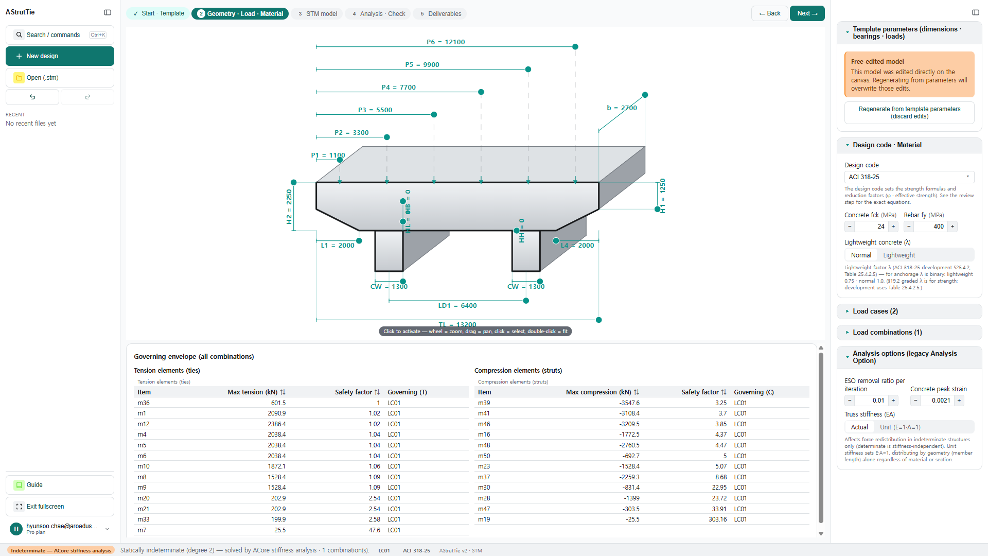
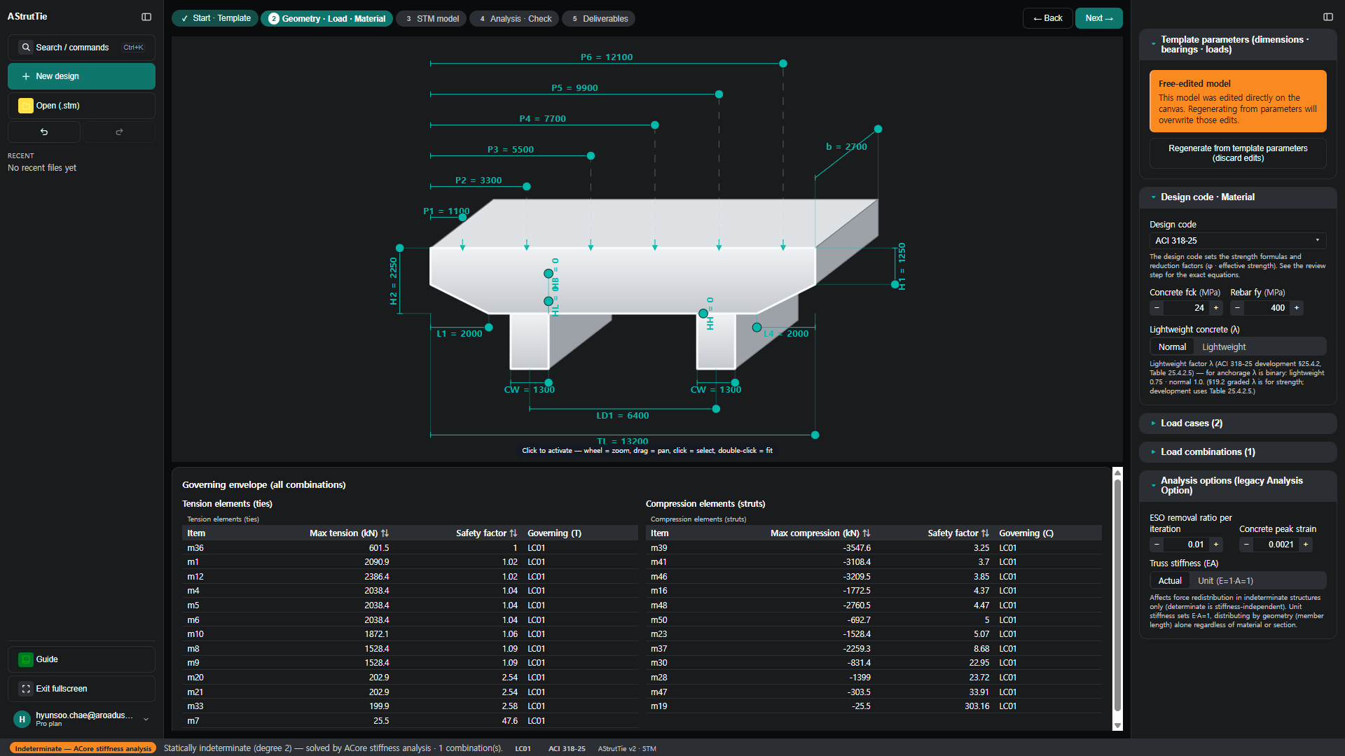
- Coping dimensions, bearing plates & service loads — entered in the template (see the drawing below)
The problem
A two-column pier coping carries the girder bearing reactions across to two supporting columns. Its geometry, bearings and loads define the design — typed straight onto the drawing.
Build the model — template → strut-and-tie
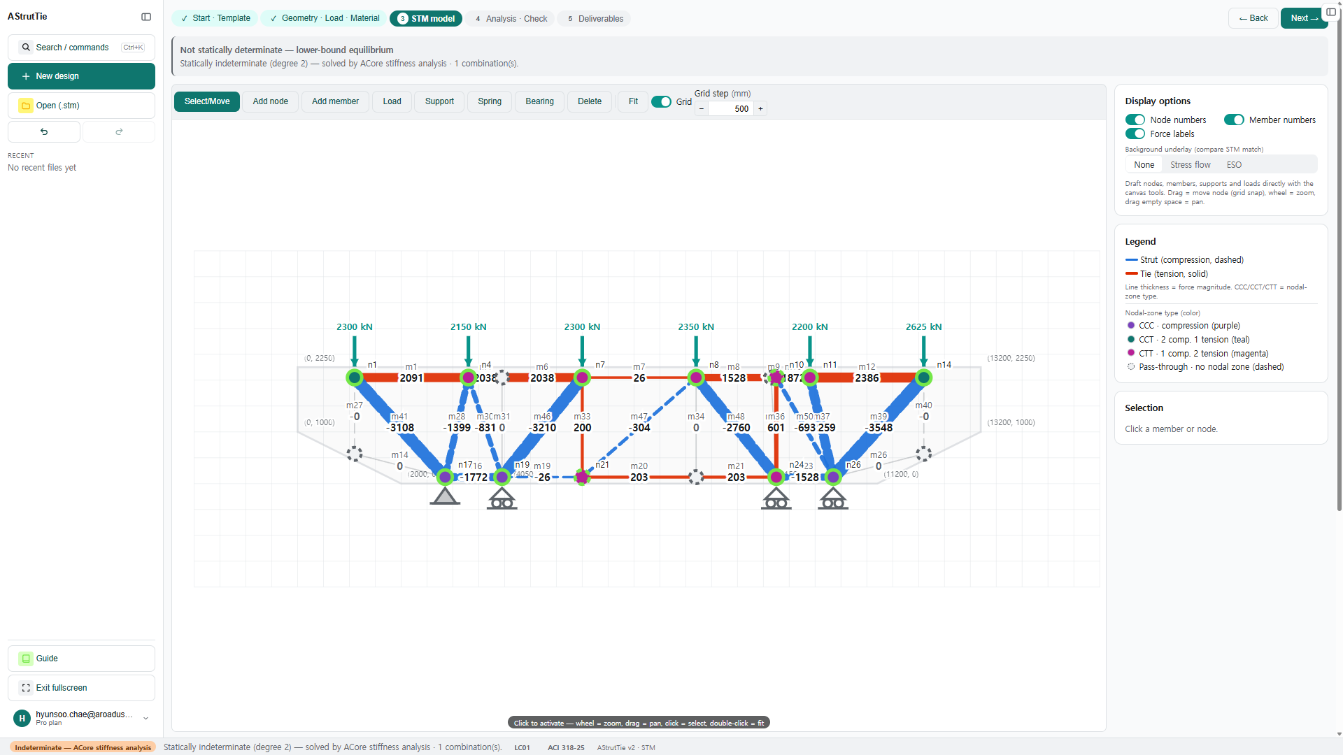
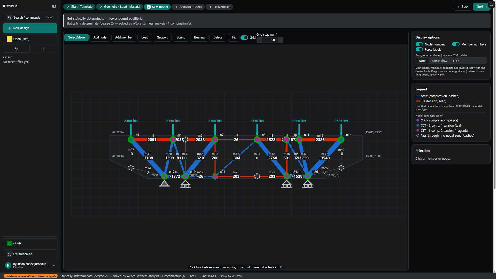
The pier-coping template builds a strut-and-tie model automatically: struts (compression, dashed), ties (tension, solid), and nodal zones typed CCC / CCT / CTT. It is then refined to follow the load path between the two columns.
Analyze & check — every member, every combination
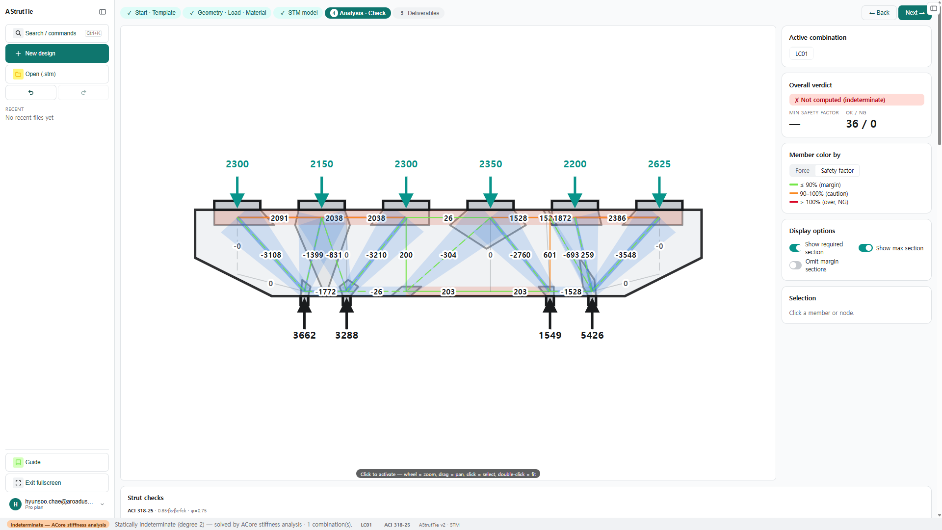
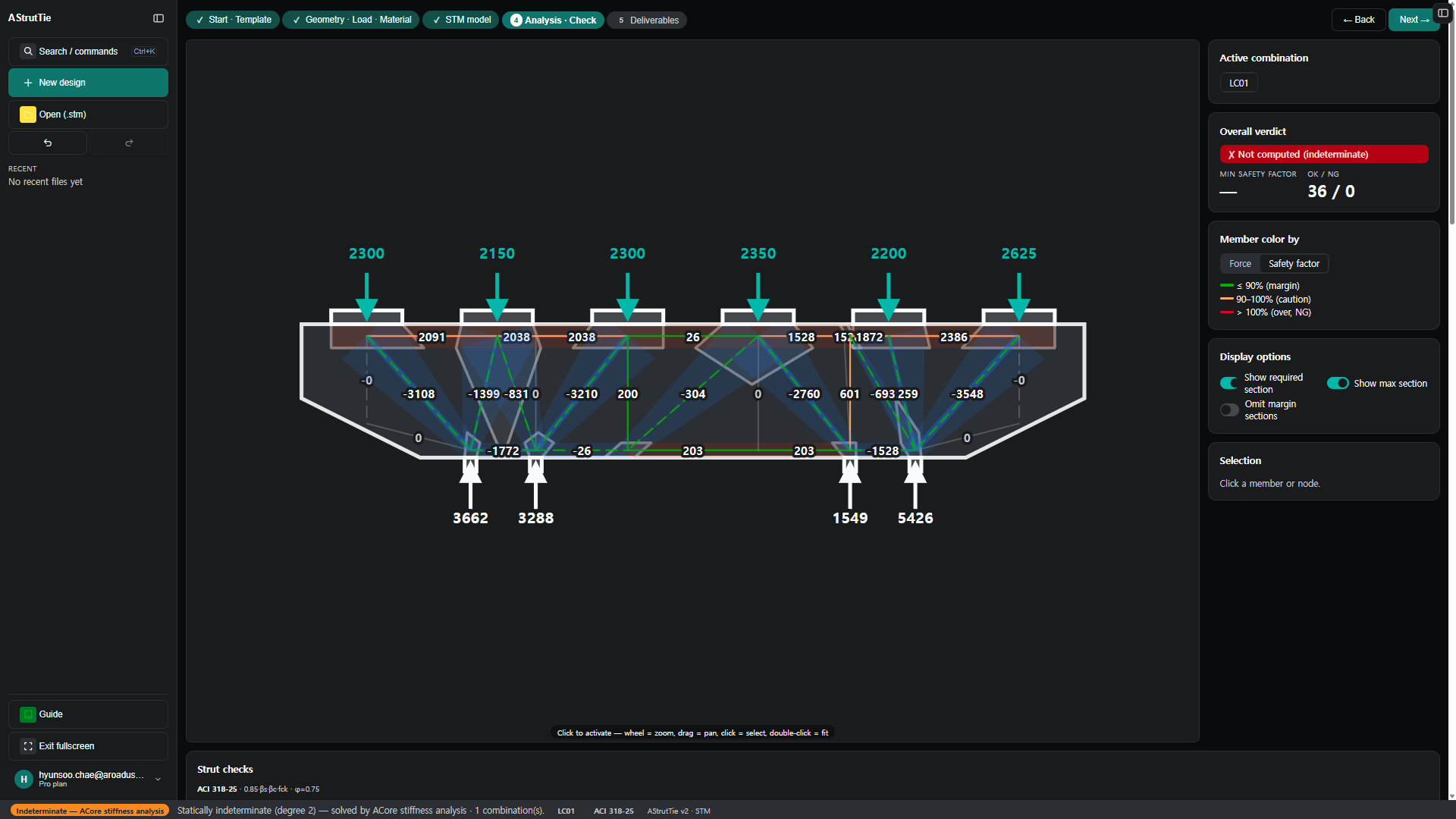
This coping is statically indeterminate (degree 2), so it is solved by ACore stiffness analysis; every member is then checked against the code — here 36 / 0.
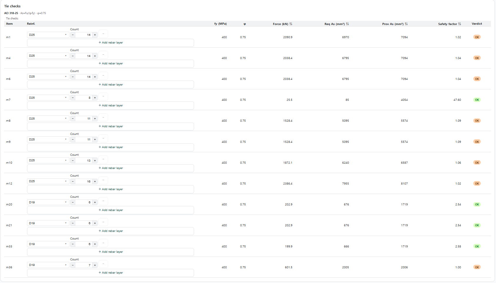
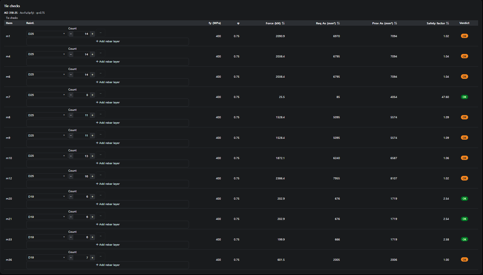
Tie check — required reinforcement
ACI 318-25Required steel As,req is compared with the provided bars (size × count). φ = 0.75, fy = 400 MPa.
Strut check — effective strength & width
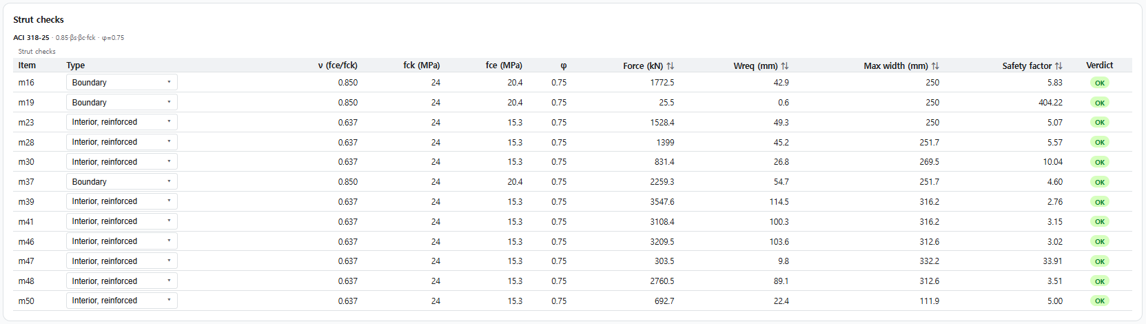
ACI 318-25Effective strength depends on strut type — Boundary (fce = 0.85 fck = 20.4 MPa) or Interior, reinforced (0.637 fck = 15.3 MPa). The required width must fit the available width.
Nodal-zone check — by node type
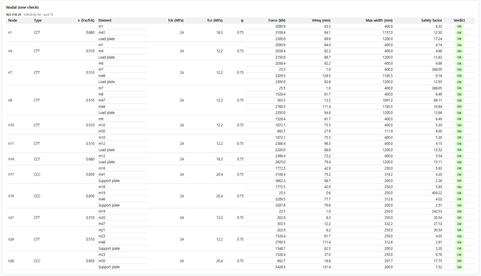
ACI 318-25| Node | βn | fce (MPa) |
|---|---|---|
| CCC | 1.0 | 20.4 |
| CCT | 0.8 | 16.3 |
| CTT | 0.6 | 12.2 |
Anchorage check — development at the node
ACI 318-25 §23.8.2 · §25.4The tie must be anchored at the node: the available anchorage ℓanc (§23.8.2, extended nodal zone) must reach the required development length ℓd (§25.4). Available = straight length along the tie plus a code hook-tail credit where a hook fits.


These are the same checks AStrutTie runs — and Technical Book Example 01 is one of the cases our verification gate holds the engine to, unsafe-side zero. How we verify →